I built a 1.35 million-volt Tesla Coil in my backyard without killing myself.
Author's note: This is an extremely dated article written in high school.
Invented by the brilliant scientist Nikola Tesla (1856-1943), the Tesla Coil is a high-voltage, high-frequency power generator. Tesla designed it to broadcast wireless electricity, but due to its poor efficiency right now they're just to look cool.
With this device, Tesla was able to generate voltages of such magnitude, they would shoot out of the apparatus as bolts of lightning! The sight of writhing streamers of electricity jumping through the air is absolutely spectacular. Today, Tesla Coils are built by amateurs all over the world for one reason only – the thrill of making your very own lightning!
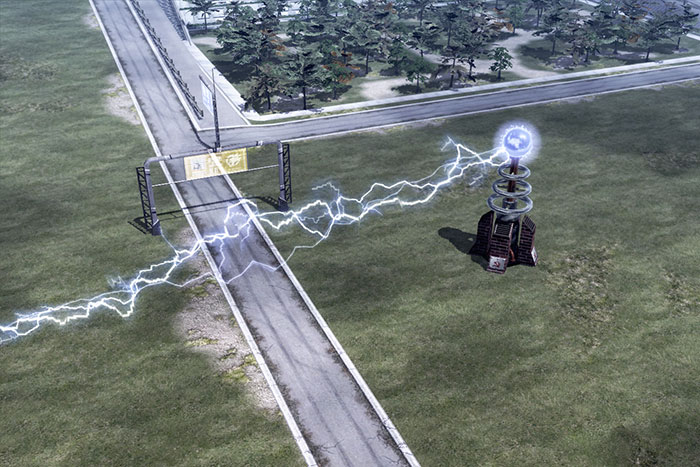
Tesla Coils were also popularized in the 90s by the hit video game, Red Alert. In the game, Tesla Coils were used by the Soviet Union as weapons to produce extremely high and lethal voltages.
Follow me
Keep up with my latest adventures
Materials
| Lots of Capacitors | Aluminium Air Duct |
| Neon Sign Transformer | Copper Pipe |
| High Voltage Copper Wires | Fish Tank Tubing |
| Sheets of Acrylic | Flexible Copper Tubing |
| Aluminium U Profiles | Lots Bolts/Nuts/Wire Lugs/Etc |
| Lots of Resistors | Electrical Tape |
| Pie Dishes | Aluminium Foil Tape |
| PVC Tubes | PVC End-Caps |
| Polyurethane Varnish | AWG24 Wire |
| Drill | Soldering Kit |
| Hammer | Threaded Rods |
| L-Shaped Metal Pieces | Rulers |
| High Density Polyethylene (Chopping Board) |
Cooling Fan |
| Saw | Fuse Holder |
| Wooden Blocks | Spray Paint |
| Wooden Boards | Too Much Spare Time |
| Motivational Posters | Money |
| Single Relationship Status |
Construction
As a disclaimer, the construction of a Tesla Coil is complex and involved. It is costly, time-consuming, dangerous and requires tremendous motivation. There are technical skills involved and a good knowledge in physics and mathematics is essential. It's best that we break down the construction into its different components.
Power Supply/Transformer
Perhaps the most important component of a Tesla Coil is its power supply, and also probably the hardest to obtain. The specifications of the power supply affects all the other components and the overall size of the Tesla Coil.
The power supply basically converts the voltage from the mains (240V) to the extremely high voltages required by the Tesla Coil.
Generally, amateurs look for a few type of transformers.
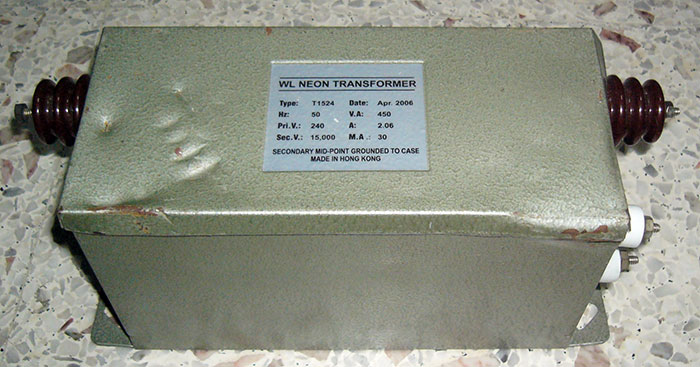
Neon Sign Transformers (NSTs) are probably the most popular. They can be obtained from neon sign shops. The cost can be from $30 to over $100, depending on the condition and ratings. They generally range from 6000V to 15000V, with about 30mA. There are 2 kinds of Neon Sign Transformers, one is iron cored and runs at 50Hz, while the other is the new smaller switchmode one which run at 20kHz and is a lot lighter. The heavy iron-cored ones usually perform better.
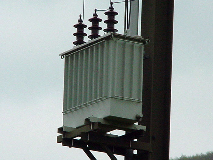
The ultimate transformer would be a Pole Pig. These are used by your local government agencies to deliver the power to the city. They can be found, well, up high on the poles that deliver your electricity. They weigh about 200kg, so if you're going to steal one, be prepared with a crane or something. Also, you may want to have an electrician with you when you run the Tesla Coil at home, as your circuit breakers will blow easily due to the high current these guys require. Basically, don't bother.
I called up a Neon Sign shop and they indeed had used/old NSTs for sale. I visited them and picked up one at S$45. If you don't know how to operate one, it’s best that you ask the shop to demonstrate. They’re deceiving small; They weigh quite heavy, coming in at about 8kg to 20kg, and my arms were sore after carrying it home on public transport.
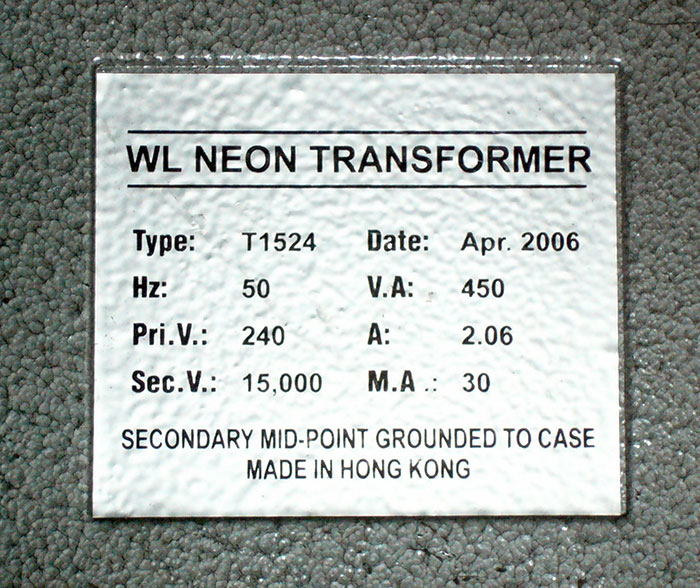
First, some details of my transformer, along with the specifications my tesla coil has to meet.
My NST outputs 15kV and 30mA.
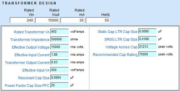
Going into further details…
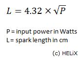
Using this formula, I worked out that my Tesla Coil can achieve spark lengths of up to 91.64 cm. Now, it won’t get to anywhere close to this value, but it just gives a safe estimate of the space I need to conduct the tests.
Capacitor Bank
Each tesla coil has to have a capacitor bank. This stores the power needed for the tesla coil to discharge. Three types of capacitor banks can be built, including a completely home-made one consisting of beer bottles and some stuff. But the easiest method would be a Multi Mini Capacitor (MMC) design. A lot of factors has to be considered for the MMC.
First, you gotta know the peak voltage the capacitor bank has to handle.
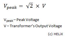
While my transformer outputs 15000V, the voltage is able to peak up to 21213V!
Then you have to choose the type of capacitor.
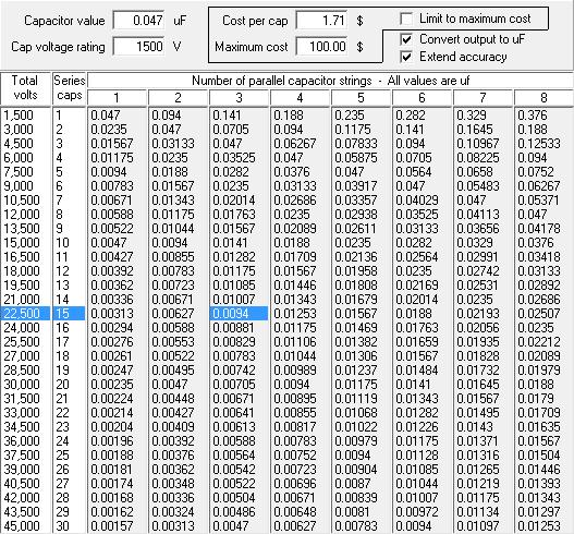
I chose a 1500VDC, 0.047uF Polypropylene Capacitor because they’re the the most value for money, ie. best uF per dollar.
Now because my MMC has to store 21213V at least, I figured that the voltages have to be split by the capacitors when they’re placed in series. I plan to arrange 15 of these caps in series, adding up to a total of 22500V that it can handle.
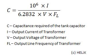
Using the formula above, I calculated that my transformer requires a capacitor bank of 0.0064uF. However, this is merely the Resonant Cap value. To be on the safer side, we would want a LTR (Larger-Than-Resonant) value. This value is dependent on whether you use a static spark gap or a SRSG (Synchronous rotary spark gap) which I will elaborate more later. I will be using a static gap, so the LTR value is 0.0095uF.
The calculated total capacitance of 1 ‘string’ of 15 caps is simply the rated capacitance of each cap (ie. 0.045uF) divided by the number of caps in the string (ie. 15), so each of my string has 0.00313uF. To produce 0.0095uF, I would need roughly 3 strings.
So it’s 3 strings of 15 caps, giving a grand total of 45 caps needed.
For each cap, a resistor has to be attached as well. Bleed resistors are employed to safely discharge each capacitor to allow for safe handling while tuning and transporting the coil. I chose a 10MOhm 0.5W 3500VDC resistor.
The overall design for my capacitor bank is as follows:

After I completed the capacitor bank, snapping photos along the way, for some reason, the images of the construction of the capacitor bank went missing, perhaps deleted/formatted, and my data recovery software wasn’t able to get them back.
So, I can’t really show pictures of how I did the capacitor bank, but I’ll try my best to put it down in words.
Ok, I drew out the layout of the capacitors on a A4 paper. Then I estimated the size of the bank, buying 3 pieces of acrylic of that size.
One piece of acrylic will be used to mount the capacitors. Holes were drilled where the ends of the capacitor were. The contact points of the capacitors were fitted through these holes to secure them firmly to the acrylic.
My soldering skills were horrible, so I had a hard time trying to solder the contact points together to form the strings of capacitors.
The resistors were then added across each capacitor. Once again, with soldering involved, the job was pretty badly done.
Finally, I drilled holes at the 4 corners of the 3 pieces of acrylic. These will be used to fit the bolts and nuts through.
The other 2 pieces of acrylic are meant to cover the capacitors for safety reasons. One covers the back with all the contact points and soldering, while the other piece covers the front, protecting me from the capacitors and them from me.
The capacitor bank lies in the portion of the tesla coil circuit where both the voltage and current are high. A thick well-insulated copper wire is require.
I measured out the needed length for the capacitor bank. The bare copper core was exposed at the different points of termination of the strings of capacitors. The end contact point was attached with a wire lug.
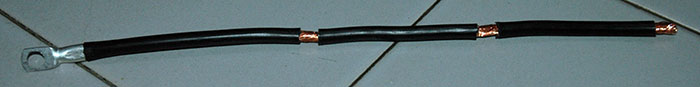
My soldering job looks like it was done by a 5-year-old.
And finally taping all the bare wiring up. It’s completed! Top view, revealing the capacitors.
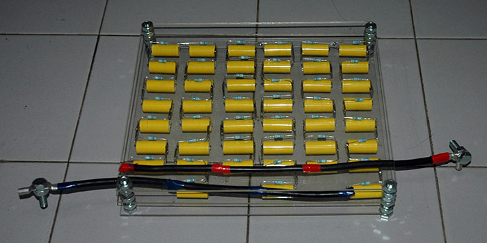
Total cost of the capacitor bank is over $100. But it’s much cheaper than buying a commercial pulse capacitor.
A week or so later, I decided to give the unfinished Tesla Coil a trial run. It turned out horrible.
The zig-zag arrangement was a dumb decision, with the current preferring to spark through the dielectric air than go through the capacitors.
Arcing was occurring between two adjacent points in the capacitor bank, much thanks to the horrible design by Yours Truly. I could add an insulating layer between the entire string of caps, but the spacing was so small that I couldn’t find a suitable material.
And so I decided to rebuild the entire thing. That was the last thing in my mind when I thought about the options, but I didn’t have a choice, it seems.
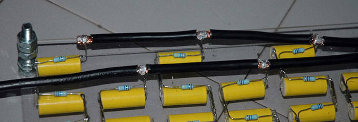
Spent about an hour or two unsoldering all the capacitors and resistors, and had my Dad to buy me new pieces of acrylic. This time, it won’t be in a zig-zag manner, it’ll just form 3 straight strings of caps.
It took a while to drill, but as I’ve done it before, it was slightly easy and faster…
Then I proceeded to insert the caps in, soldering them together.
And of course, adding the resistors…
The connections at the end are made by soldering a thick wire to the 3 contact points.
Wiring
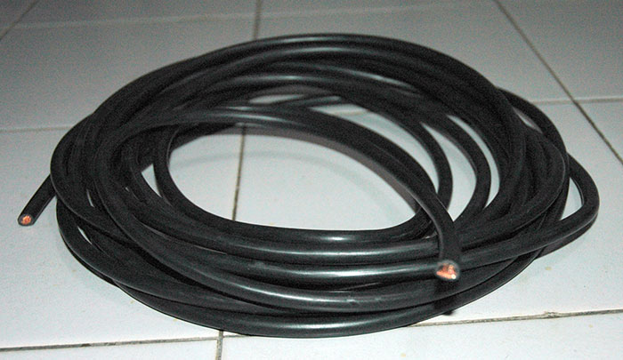
For tesla coils in general, thick well-insulated copper wires are required due to the high amount of current and voltage passing through. The amount of processed copper in the wire makes it really expensive. I asked for one with a diameter between 6-8mm, 7m of it, and the guy gave me a 7.2mm one and quoted $47. I couldn’t afford to pay that much for the wiring alone, so I asked for another smaller one. It’s about 3-4mm, not quite what I wanted, but half the price. So $20+ for thick wiring.
So when I did another test run, this happened:
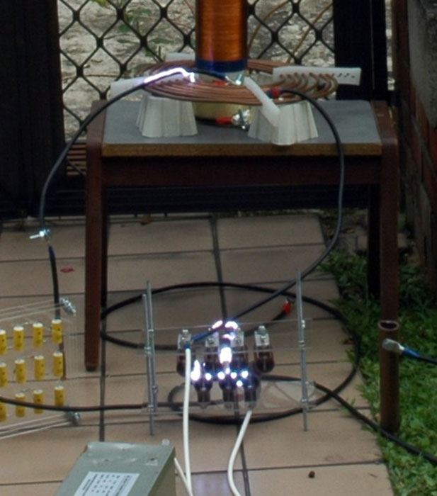
No sparks at the discharge terminal, but at the primary coil instead!
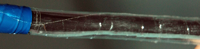
As you can see from the above picture, the arcing is actually at the wire. Yes, the 20,000 Volts just jumped right through the insulation of the wire. I thought it was rather thick actually, but no, I should have gotten HV Wires (High Voltage) but that’s pretty expensive.
So to solve this, I bought some fish tank tubing to thread over the wires, as extra insulation. All wirings are now insulated with fish-tank tubing.
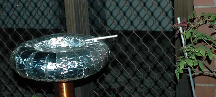
Discharge Terminal
At the top of a Tesla Coil is a discharge terminal, which is exactly what it does. One, as the name suggests, is to act as the output terminal for the streamer discharges, and the other is as a capacitive load for the secondary coil.
There can be two shapes: A toroid or a sphere. I’m not aware of the difference and pros and cons between the two, but I have no idea how to go about making a large metallic sphere. So a toroidal design is chosen.
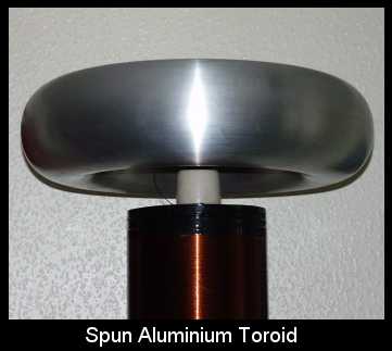
A commercial aluminum toroid would come in at a few hundred, if not thousand of dollars. A homemade one comes in at about $40.
This is how I go about doing my toroid.
3 things. Aluminum air ducts, I got 3m of it. Quite expensive at $30+. Then aluminum tape. These are about $10. And lastly, pie dishes, dirt cheap.
Drill a couple of holes at the center and near the edges of the pie dishes, and then tighten them together with bolts and nuts.
Measure out the required length of the aluminum air duct and cut it out. I used the aluminum tape to tape up the ends of the air duct, forming a tight fit around the pie dishes.
I smoothened the appearance of the toroid adding tapes from the aluminum air duct to the pie dishes.
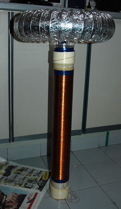
Secondary Coil
The secondary coil is one hell of a thing.
It is responsible for generating the very high voltages required and its construction is extremely tedious.
First, a coil form is required. The wires coiling about a thousand turns will completely wrap the coil form, which has to be of an insulating material. Metal pipes are totally out of the question for obvious reasons. Water is a performance killer, so cardboards are avoided as well. Most plastic materials would do fine. Generally, PVC pipes are used because they are easy to find. Some tesla coilers have attempted and succeeded, to coil the wiring around a coil form and remove it altogether, but that’s beyond my capability for now.
Black PVCs must be avoided because they contain carbon, gray works, but white does the best job.
I bought a 3-inch PVC pipe, 2 feet of it. When buying the coil form, it is important to choose the correct length for it will heavily affect the height of the coil. Too high, too bulky; Too short, the tesla coil is capable of striking itself. The diameter-to-height ratio comes into play here. I had a calculation error, so I resulted in a weird 1:6.67 ratio. Pretty bad for my coil I guess, considering the recommendation is between 1:3 to 1:6 ratio.
Before we begin, it is advisable to coat the coil form with polyurethane varnish.
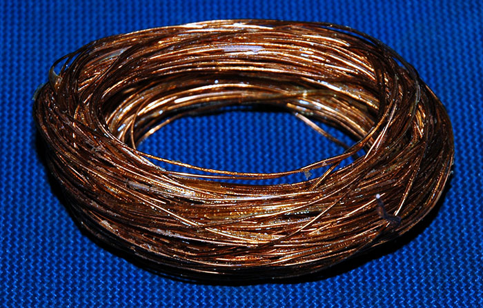
A layer or two was applied and after it dried, I went straight to wounding the wires.
A few things to take note. We should be aiming between 800 to 1200 turns, any higher or lower seems to decrease the output (either due to increased resistance or low inductance). I’m aiming for 1000 turns.
I bought 0.5kg of 0.5mm (AWG 24) wire (quite expensive at $30+). 1000 turns should give 20-inches.
The wounding is tedious. I’m looking for a word with similar meaning to tedious, but with a greater degree of suffering. But tedious would do for now. To give you some perspective, here's the process:
To begin, I found a towel hanger thing lying around. Ok, not exactly "lying around", but it took it from my mom.
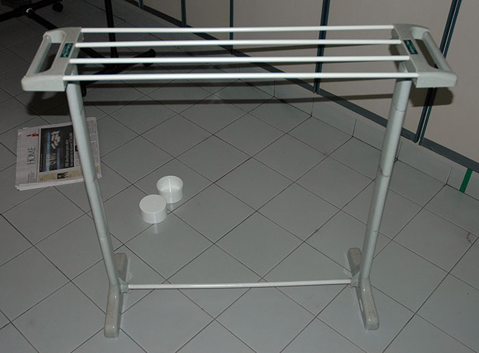
Tearing it apart, and reconstructing it, I got this little innovative thing.
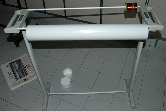
The winding was incredibly tedious, insofar that I resorted to this.
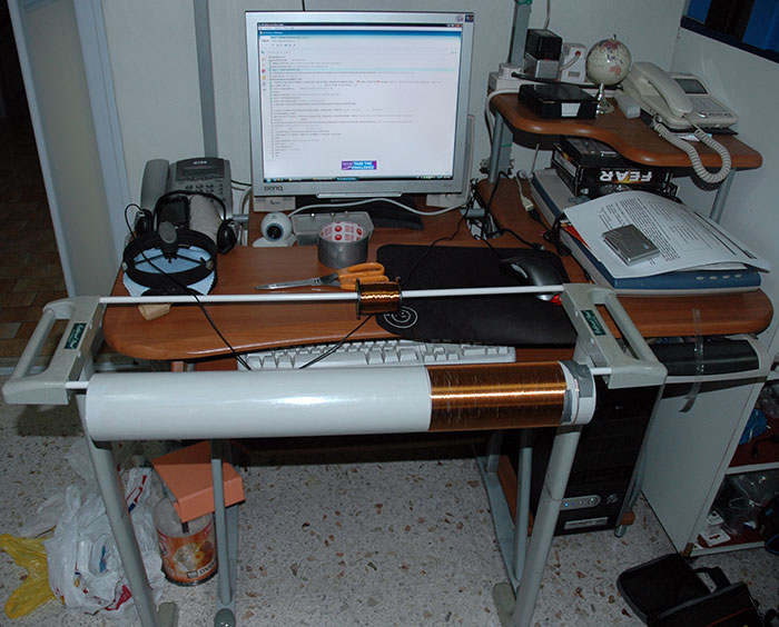
I spent 5-6 boring hours winding and winding. For entertainment, I had the the thing done in front of my computer as I watch all the remaining episodes of CSI and Lost I had left.
Started at 5pm, and about 11pm, it was this:
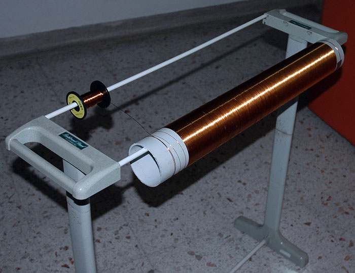
I calculated, and I figured that I wounded about 240m of copper wiring. Oh the pain!
I started off pretty well actually, with the windings nice and tight. I lost my patience midway and it got sloppy from there. Hopefully, it won’t affect the performance of the coil too much.
I haven’t finalized the design of how the secondary coil is going to be attached to the toroid, but it should look like this.
As I mentioned earlier, I found out that the number of turns on my secondary coil was too large, almost a 1000 turns. This gives too high of a form-diameter-to-coil-length ratio of 6.67. The recommended maximum ratio is 6, which I’m way above. I decided to spent a while uncoiling the turns to give a 18-inch coil length from 20-inch.
Secondary coil’s termination is done by attaching it to some aluminium tape, and using a hole puncher to allow connection to wire lug end of the ground wire.
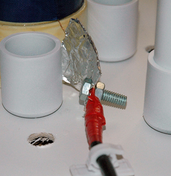
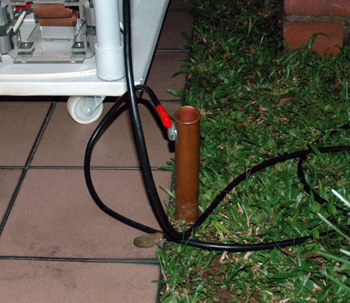
Ground Rod
The ground rod, even though it sounds insignificant, plays a major role. Most components are required to be grounded, not only for safety reasons but for them to work. I decided to have a single ground rod with many connections to it, as I didn’t want too many rods to hammer into the ground.
I started with a thick length of copper wire and a foot long of 1-inch copper pipe.
I simply drilled the copper pipe, fitted in a bolt and nut, and attached the copper wire with a wire lug at the end.
The ground rod would be hammered into the ground, securely and deeply.
Spark Gap
The Spark Gap acts as the power switch for the primary tank circuit. It uses the air to conduct electricity between its electrodes and generates a great deal of heat in the process.
Sounds simple enough, but the Spark Gap is the single component I spent the most time on. About 20 hours easily. There are many designs of Spark Gaps out there, and it was pretty difficult to decide on one.
There are two main types of Spark Gaps. A static one which does not involve any movement of electrodes, hence the name. And an exotic type that involves the electrodes rotating to provide better performance. The schematics for the rotating spark gap was too complicated, so I settled on a Static Spark Gap.
The design for a Static Spark Gap could vary from a simple one like:
However, the gap is usually split into lots of smaller gaps, all wired together in series. This is done for two reasons; 1) The more gaps you have the more power it can handle; 2) It is possible to vary the firing voltage of the gap by changing the number of electrodes that are in circuit (by moving the connecting wires).
In doing this, you get a Multi Series Static Spark Gap, which was what I chose to built. This design for this varies a lot, and it makes a big difference in price, efficiency, feasibility, time spent, etc. Different people would have different preferences in the large number of designs available. After hours of searching the web, I found a design that appealed to me. It’s by a guy called Scott. Which Scott, I don’t know, but how many Scott’s are there who’s a Tesla Coiler?
So, I got started on it.
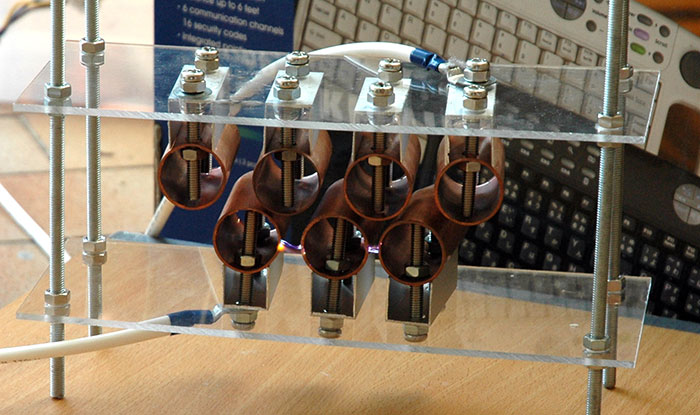
Two pieces of clear acrylic, drilled, and supported by threaded rods at the 4 corners. The threaded rods were really irritating to saw and file.
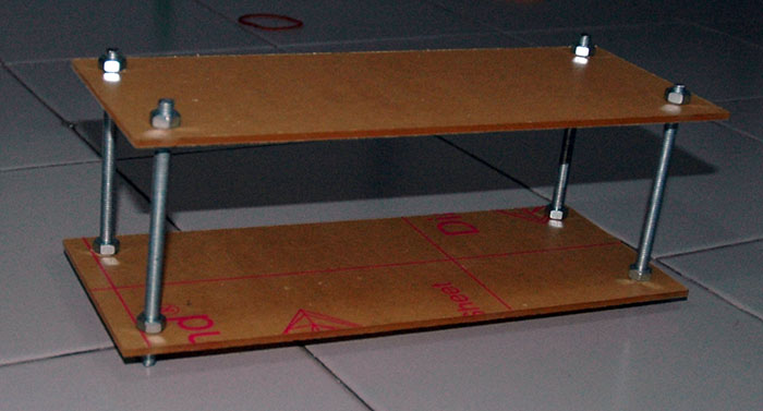
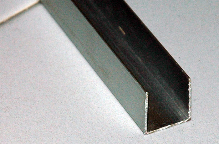
I found Aluminium U-Profiles of the correct size! Once again, sawing was really a pain.
And aligning them…
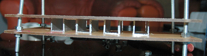
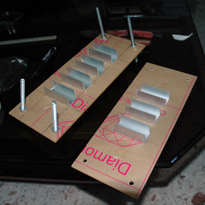
The electrodes! Copper pipes, held from the acrylic by Aluminium U-Profiles.
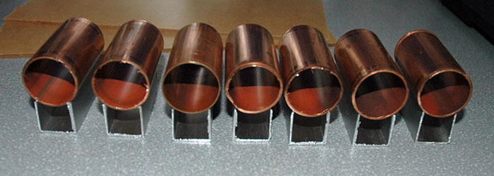
After hours and hours of drilling…
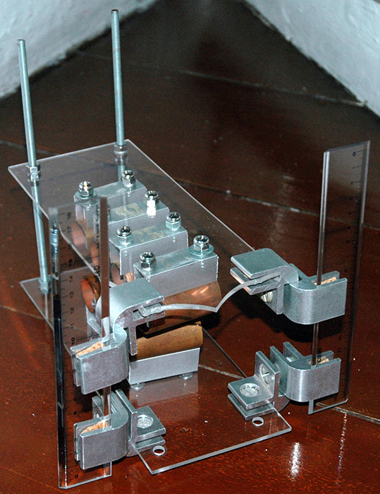
The final assembled Multi Series Static Spark Gap! The connections were attached to the bolts and nuts supporting the copper pipe and U-profiles.
Then more frustration. In one of the test runs, while putting away the setup to conclude the day, I dropped the Spark Gap. It broke quite badly and looked like it’s completely out of order. I spent over a whole afternoon and probably more on that spark gap, something like 6 hours of continuous tedious technical work, and seeing it break was a totally sucky feeling.
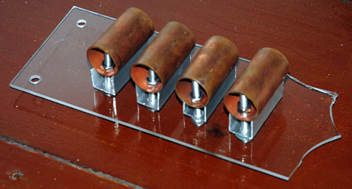
I had to build another, but I told myself, “no way not another 6 hours of drilling, sawing, etc,” and so I improvised. Came up with a new design, and with it, had a chance to made things better.
I found these L-shaped metal pieces somewhere in the house, and came up with a idea. I asked my Dad for more, and he took out an entire box of it.
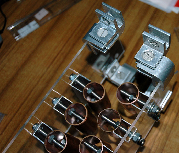
And I bought 2 solid plastic rulers to act as the support, and it also provides precise measurements for the distance of the spark gap.
The spark gap has to be tuned to allow the Tesla Coil to achieve its maximum performance.
To do this, I connected the spark gap only to the 15000V transformer. From there, I adjusted the distance between the electrodes such that I achieve the maximum distance of the spark gap, which corresponds to the maximum voltage passing through.
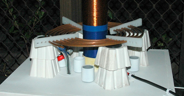
Primary Coil
The primary coil and the main tank capacitor form the primary resonant circuit. For proper operation, a Tesla Coil must have identical primary and secondary resonant frequencies.
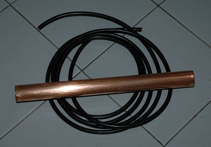
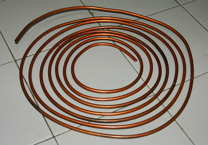
There’s not a lot you can say about my primary coil. Basically, it’s a coil of copper pipe, wound in a flat pancake spiral. The diameter of the inner-most turn should be 2 inches greater than the diameter of the secondary coil, and it spirals out keeping a 1/4 inch gap between adjacent turns. The total number of turns required depends on the values of the other circuit components, but a maximum of 10-15 turns would be a good number.
Copper tubing, normally used for central heating systems, is ideal for making primary coils. It has a large, smooth, surface area which is ideal for high frequency/high voltage use and it’s easy to bend by hand.
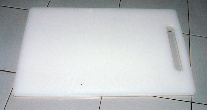
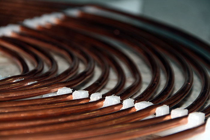
A good material for mounting high voltage components on is high density polyethylene (HDPE), and it’s easy to get hold of in the form of a chopping boards. This is what I will be using to support the tubing. If you use wood, it should be dried out and sealed with varnish to ensure it acts as an insulator.
First, I cut out strips of HDPE with a saw.
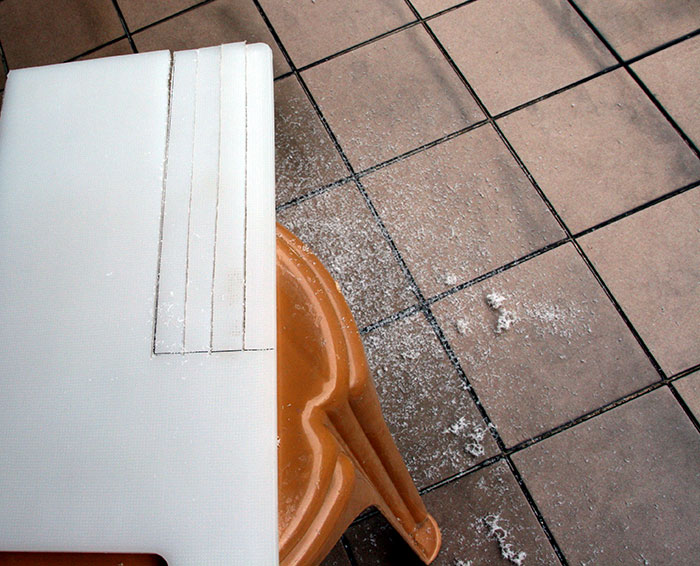
Following which, I drilled holes in all the strips which will be where the copper tubings go through.
So I sat down in front of the TV and started to thread the supports through the copper coil.
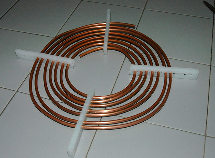
And then it’s done!
Many weeks later, when I successfully tested the tested coil, I managed to achieve 25-27 cm arcs… but the performance of the tesla coil was limited.
The problem was with the primary coil. I had the primary coil tapped at coil number 8, with improving performance as the number of turns increase. My primary coil, sadly enough, was a total of only 8 turns. My tesla coil’s performance was bottlenecked by, of all things, my primary coil!
If I had a longer copper tubing, thus more turns in the primary coil, I should be able to squeeze out a lot more performance. It’s a big pity that the Primary Coil is limiting me from achieving resonance.
So, I bought a new 50-foot copper tubing for my new primary coil. Compared to my 18-foot old primary coil, this should never run out of turns for me to tap from.
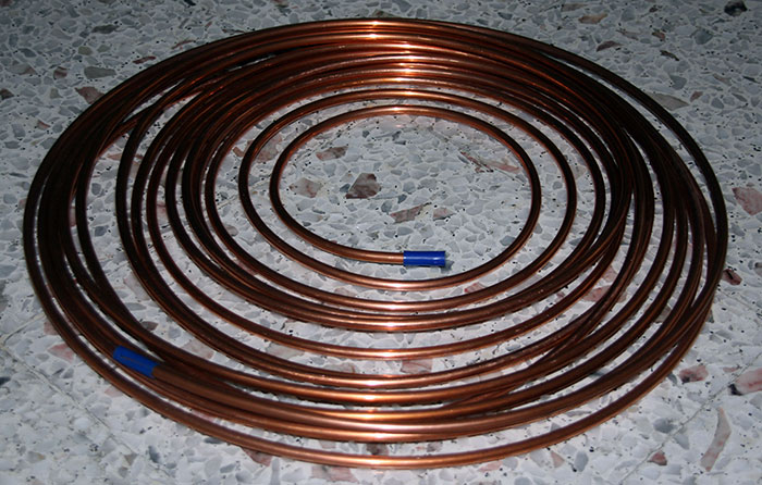
Spent an entire afternoon working at it. After 4 hours of sawing, drilling, hammering.
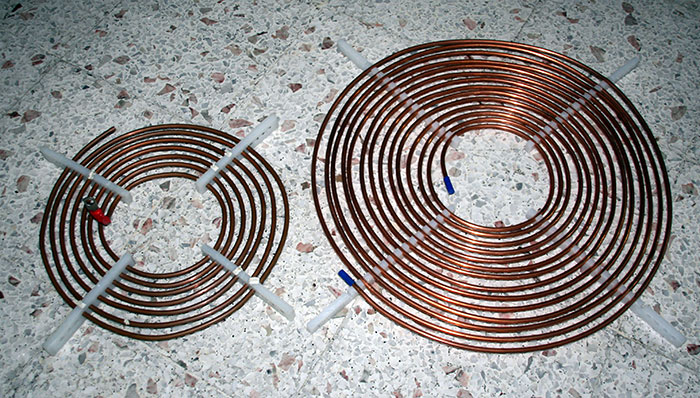
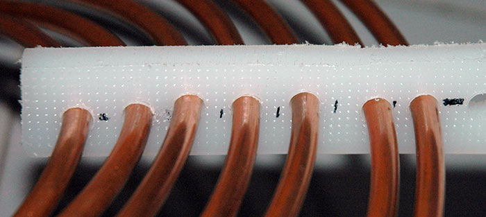
I did do it a little different this time, because I learned from experience. Threading through the supports was going to be painfully tediously, so I got smart and did it a different way. Instead of threading it through, I simply made tight ridges with small openings in the supports. From there, I can just push in the copper tubes to fit nicely into the supports’ ridges.
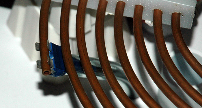
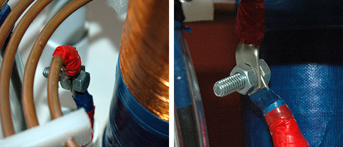
There are two electrical connections to be made to the primary coil; a fixed connection at one end of the coil and a movable tapping point, to connect to any point on the coil. This is what enables us to tune the frequency of the primary tank circuit to match the natural resonance of the secondary circuit.
The moveable primary tap connection was made from a fuse holder. It was designed to take fuses but with a bit of careful bending with pliers, a good connection to the copper pipe is possible. It actually took a lot of modifications for me to get it to connect well with the thick copper wire.
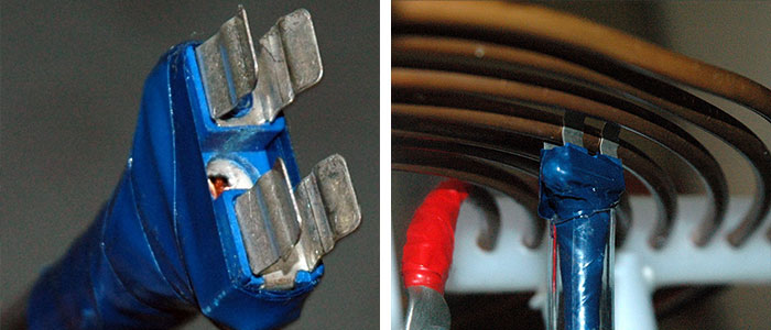
The fixed connection is made by twisting the inner end of the copper tubing downwards, and I taped on a wire lug to ensure good electrical contact.
Stand
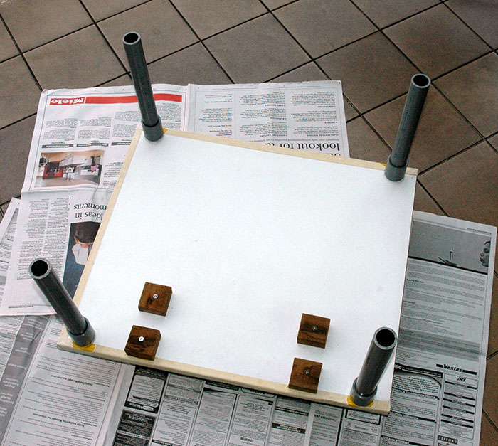
I decided to build a proper stand for easier setup, better looks, and more manageable for storage when I’m done with it. So a few weeks ago (almost a month actually), I got my Dad to do up a stand for it. I described to him what I wanted: Two-decks, 4 supports, on wheels.
After a week or two, he got it done, but I kept requesting for minor fixes and changes. It was looking really ugly with yellow, white, gray and brown. The 4 supports are PVC pipes, and the wooden blocks are used to hold things in place.
If there’s one thing I learned from Apple’s iPod, it’ll be that Immaculate White looks awesome.
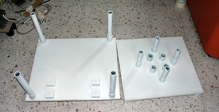
S$9.00 on white spray paint. Stupid iPods teaching stupid things.
I spent almost 2 days mounting the Tesla Coil permanently into the stand. I had to drilled more holes, add more wooden blocks to hold stuffs in place, drill in hooks, adjust the length of wires to fit the structure nicely, etc, and finally spray painting it white again.
The design had features and stuffs that include:
A hook to hold the long ground wire and the ground copper rod. So it’s much more manageable and convenient now.
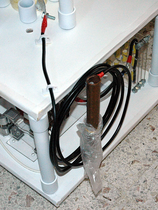
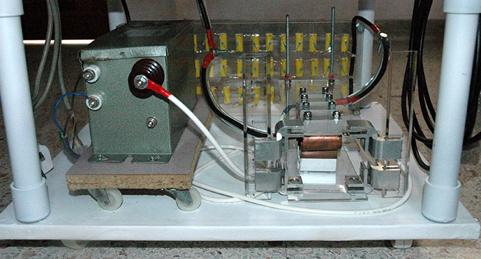
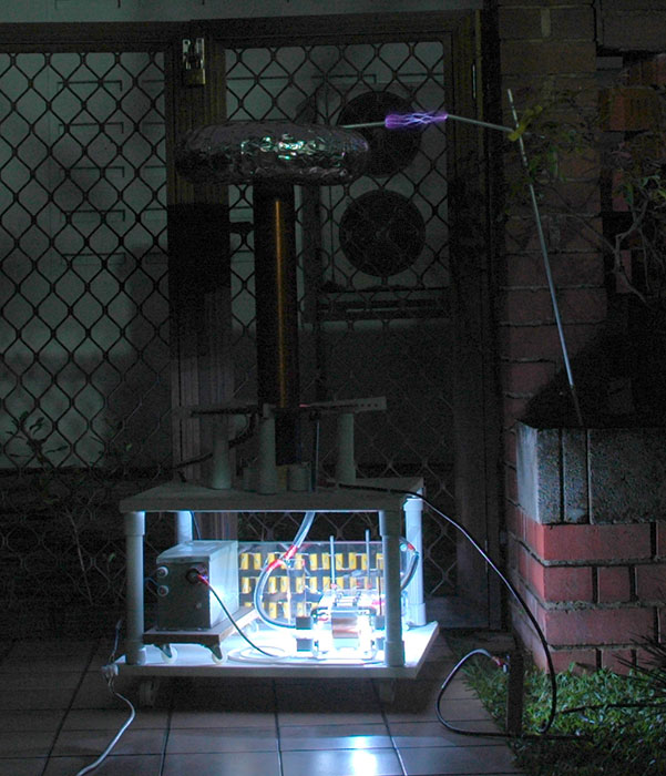
The 15kV transformer, Spark Gap and Capacitor Bank arranged nicely in place in the lower deck. All cables are insulated with fish tank tubing, and adjusted shorter to keep it neat and tidy. The transformer is also on wheels, as I can’t move the Tesla Coil setup with it on. The transformer alone is possibly heavier than the rest of the Tesla Coil.
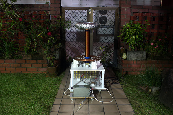
The toroid mounted firmly on top of the secondary coil.
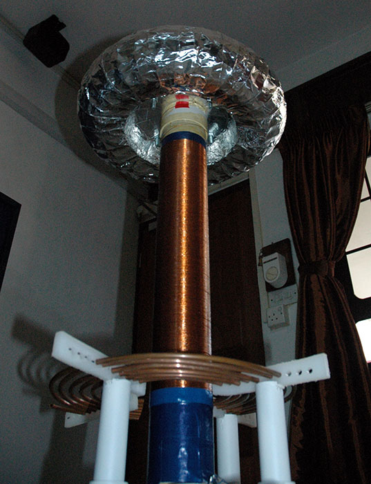
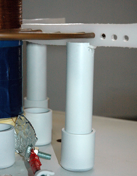
The primary coil is supported by 4 PVC pipes.
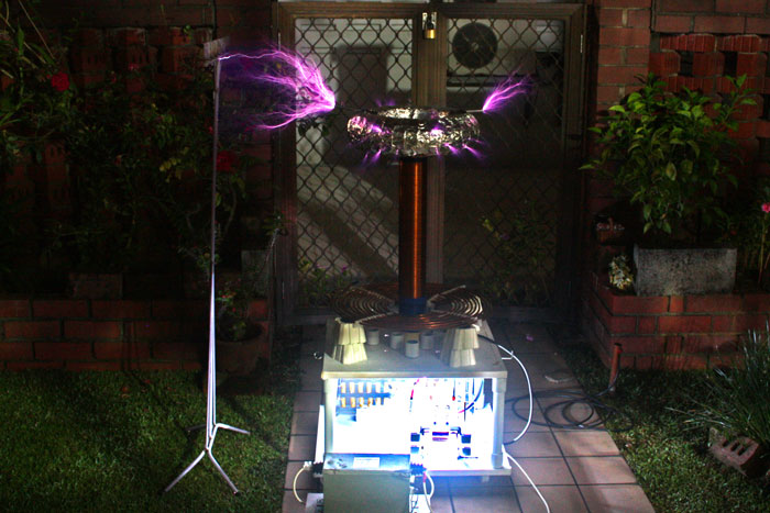
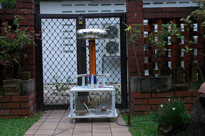
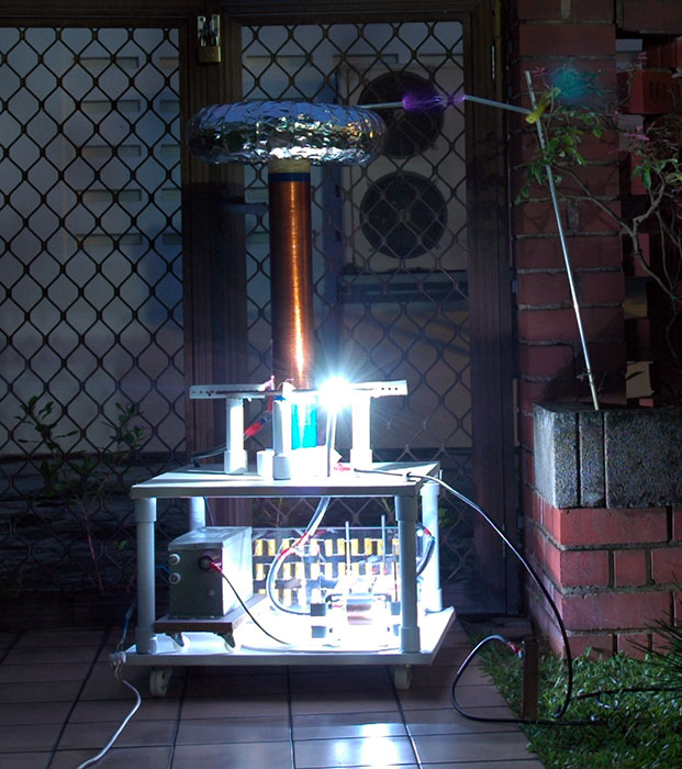
And finally, the fully completed setup of the Tesla Coil.
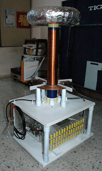
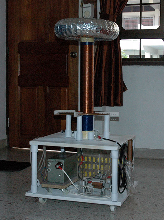
Beauty, isn’t it?
Tests
I made a lot of test runs with the whole setup assembled, and about half of them were failures. But I will not document all of them. Instead, only the successful tests are found below.
Test 1: First Light
After encountering so many problems and setbacks with all the previous test runs, I entered this test with the mindset that it’s-gonna-be-another-trial-run-with-problems-which-I-have-to-fix.
The spark gap was not tuned at all, but I fired up the full setup anyway. Primary coil was tapped at turn 7. It was quite late, about 8pm+, but I needed the darkness.
…and POWER UP!
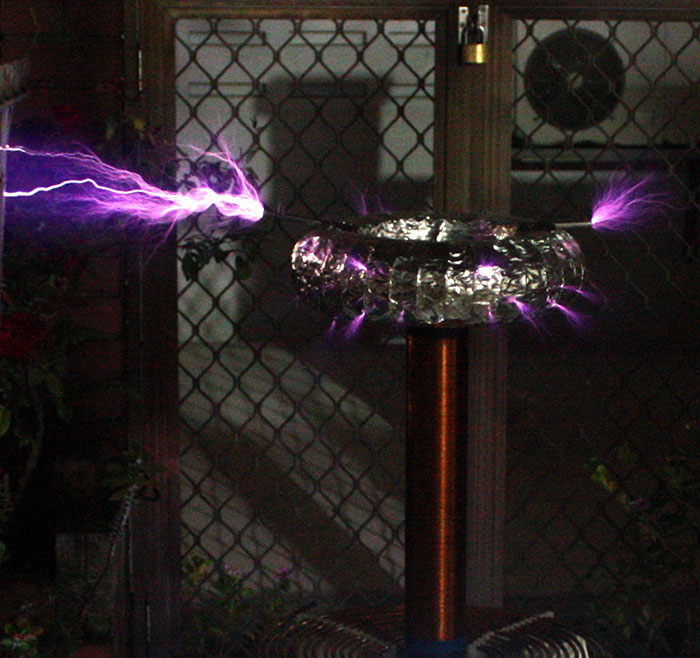
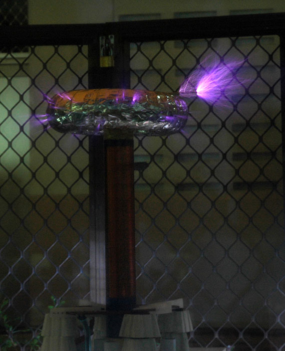
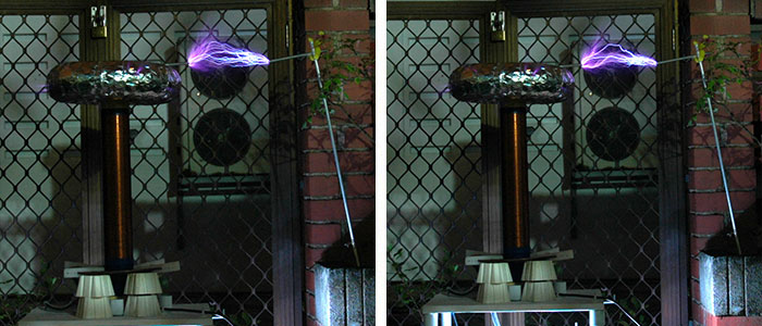
The spark gap was sparking very loud; dangerous thing to stare at as it produces ultraviolet rays. But the awesome spark at the discharge terminal is much, much more beautiful.
A zoomed-in image.
Wonderful performance! Finally, first light from the discharge terminal!
With proper tuning, I’m pretty sure it’s performance can maxed out at about 3-5 times of this trial run.
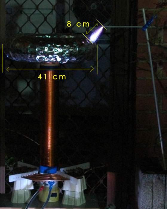
I measured the diameter of the toroid discharge terminal, compared it to the spark length in the photo, and estimated it to be a 8 cm.
As I do not have access to any feasible method of measuring the extremely high voltage, let’s make some rough estimates.
In an electric field (generated by the toroid-shaped discharge terminal), the electrical breakdown of air corresponds to roughly 30,000 V/cm.
The 8 cm arc photographed is therefore about 240,000 V. This is, of course, quite inaccurate as the value differs with many factors such as electric field, shape of electrodes, atmospheric conditions, etc.
In theory, it is also possible to work out the voltage by calculations. This will only give the maximum output voltage only, which I hope to achieve after I’m done tuning the coil.
Using, Vmax = Vcap * (Eff * Lsec/Lpri)^0.5
Efficiency of the coil is taken to be a reasonable 85%.
Inductance of secondary coil, Lsec, is calculated to be 8.38mH = 8380uH.
Inductance of primary coil, Lpri, is calculated to be 13.05uH.
Vmax = 21200 V * (0.85*8380/13.05)^0.5 Vmax = 495,300 V
This formula somehow gives my coil a poor max spark length of 16 cm. When using another formula (available above, under Power Supply/Transformer), it worked out to be 91.64 cm.
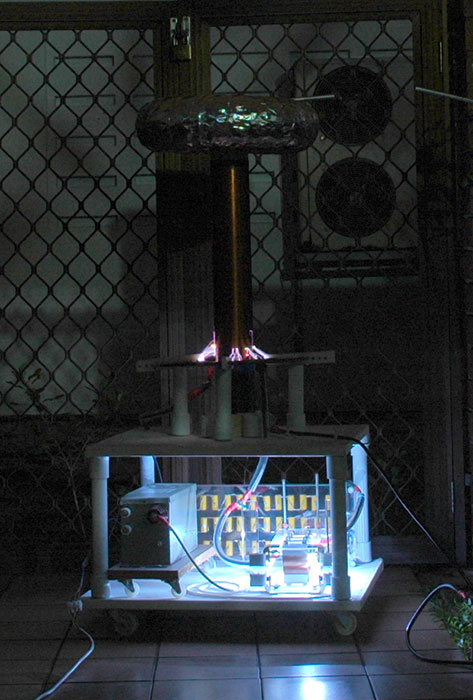
Test 2: Limited by Primary Coil
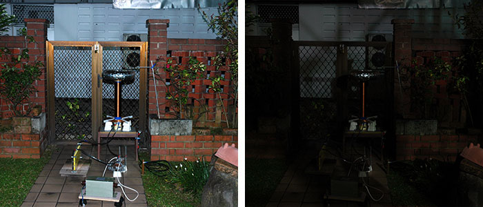
6pm, I decided to drag my whole Tesla Coil setup outside. Fixed up some stuffs, set up the camera, warned my siblings/parents about the noise I was going to create, hammered in the ground rod…
By then, it turned dark…
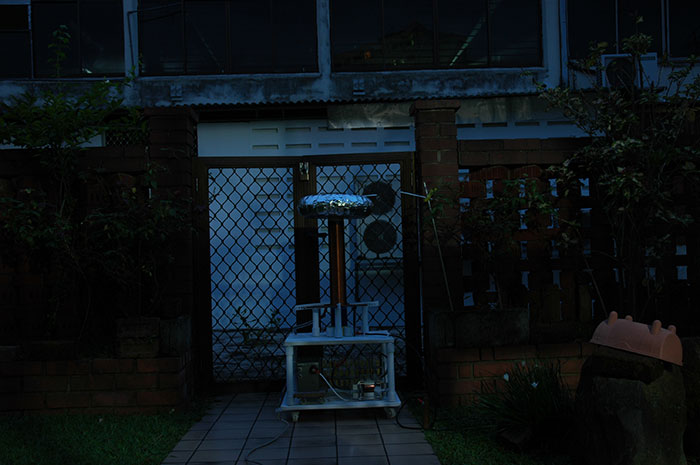
I always hate hammering the ground rod. My backyard garden qualifies as a golf course now.
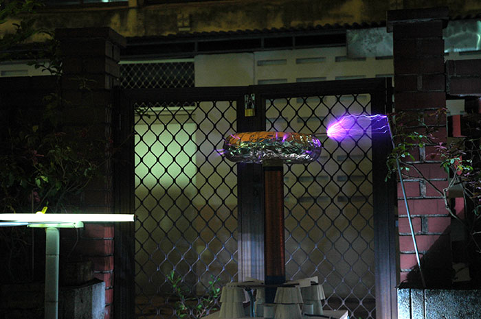
The breakout point is simply an uninteresting aluminum rod taped to the toroid. The streamers would erupt from this breakout point, rather than sparking around randomly.
And I fired it up!
Stupid me. I didn’t even connect the Primary Tap to the Primary Coil. The result? Serious sparking as the current attempts to complete the circuit.
What I found incredible was that, despite the massive energy loss in the sparking, the coil was running! See the top for the breakout point faintly arcing to the grounded rod on the right.
So I fixed the Primary Tap problem and tried again.
Racing sparks appeared. This happens when there’s a spark from the primary coil to the secondary coil. And for over a while (through many attempts), it became a serious issue.
Racing sparks occur when a coil has one or more of the following:
– Overly high coupling
– Overpowered system
– Poor quenching in the spark gap
– Out of tune, too large toroid
– Overly large primary cap
Doesn’t matter which mine happens to fall into, but I didn’t like it.
I had no choice but to change the level of the Primary Coil, making it lower. That would be dealing away with the PVC Pipes supports (which I spent lots of effort into) and going back to temporary supports.
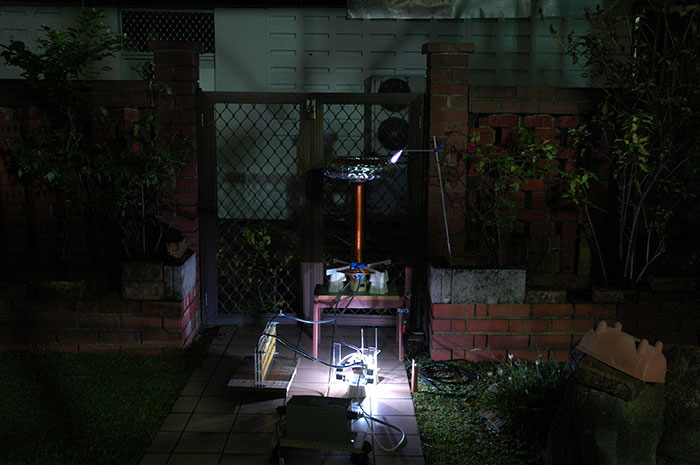
And it worked perfect!
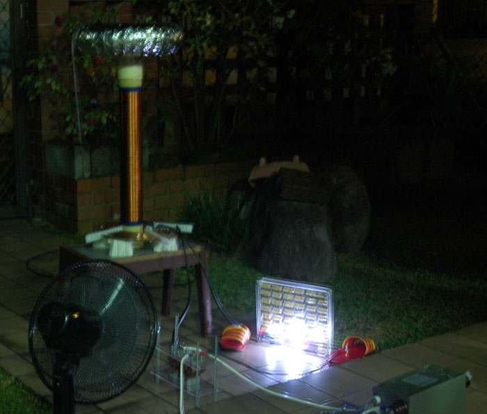
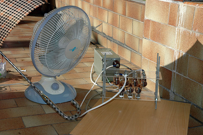
I decided to place a Fluorescent Lamp next to the setup. It’s completely not connected to anything. Just lying there. And MAGIC!
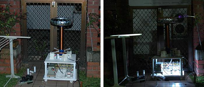
Okay not really if you know a thing or two about electric fields.
The electric fields of Tesla Coils (yes, even the homemade ones) are know to be so powerful that it can interfere with TV signals and render any digital devices you’re wearing useless. Most commercial Tesla Coils are placed in a Faraday’s Cage, as such.
With everything FINALLY working (almost over an hour), it was time for tedious tuning.
I had to tune the Primary Coil’s frequency to match the Secondary Coil’s, so that they are in resonance, producing maximum power. This is done by changing the position of the Primary Tap at different points in the Primary Coil.
And I started to tune, and removing the breakout point…
And back with the breakout point in position:
Usually, Tesla Coilers have to find the perfect number of turns to tap the Primary Coil at. Too many turns, or too little, resonance will not be achieved.
Mine was a different case. It started like this…
When I went out to purchase the components for my Coil, I bought the Flexible Copper Tubing to make the Primary Coil from some old lady. Previously, I was told that the price of copper has sky-rocketed in recent years. She charged me $12 per meter, I bought $66 worth of it.
When I did my Primary Coil, it gave me 8 turns, which is quite little. But I guess, I couldn’t afford more. One day, I was told that I could get the Copper Tubing at $25 for 50 foot. And that the old lady cheated me.
Grah. I could have gotten over twice the number of turns with $25, as compared to 8 miserable turns with $25.
Back to where we were, and so, I realised that the performance of the Tesla Coil increases with number of turns. At turn 7, a spark of 25cm was achieved.
So I had the Primary Tap at Turn 8, the maximum.

If I had a longer copper tubing, thus more turns in the primary coil, I should be able to squeeze out a lot more performance. It’s a big pity that the Primary Coil is limiting me from achieving resonance.
As much as I wanted to end the Tesla Coil project once and for all today, I think it’s wiser if I get a new longer tubing, and tune the Coil to it’s maximum performance, and not limited by the primary turns. So this project will be extended again.
Today’s maximum spark was about 25-27 cm! With my Coil at 450W, I should get at least 40-50 cm sparks. But it’s the best performance so far.
The sound from the Tesla Coil is frighteningly loud. I managed to run it quite a lot of times today (over 10 times, I believe) because the neighbours on the right were away from home. I forgotten about the neighbours on the left, so they heard it and thought it was their house alarm (Yes! THAT loud.). So they removed the batteries from their house alarm, and went back to doing their stuffs. Imagine what happened when they found me. Urggh.
Here are the results for today!
Test 3: Finale
Within weeks of Test 2, I fixed the primary coil by making a brand new one. However, it was going to be months before I could do any tests with the new primary coil due to all my commitments and school work.
When the June holidays came, my family decided to go on a trip to Europe, thereby postponing my plans to finally complete the Tesla Coil, once and for all.
So, another three months later, came the September holidays. Perfect.
I took out the Tesla Coil, covered with a visible layer of dust after being untouched for SEVEN months.
The copper of primary coil was evidently oxidised, with a darker and less reflective appearance. This may decrease the performance, but I went ahead anyway.
Also, the spark gap became loose. I didn’t want to waste any time tuning it to perfection and maximum performance again, so I simply tightened it and connected it into the the system.
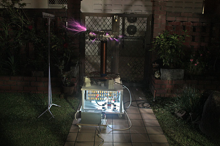
After some thorough cleaning up, I brought the setup out to the backup and I was good to go!
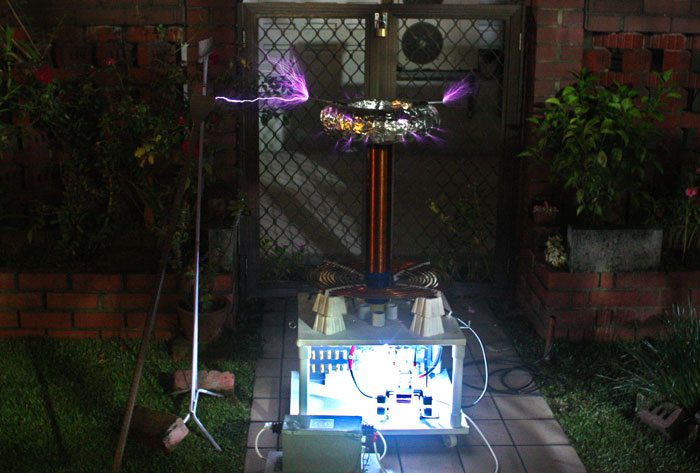
The Tesla Coil started off with a really weak display…
Then I adjusted the primary tap to tune the coil…
I went from Turn 9.5 to 8.5, and found that it increased the performance quite significantly. I went on to 7.5, but the performance dropped, but not as much as if it were in Turn 9.5
So I estimated that the ideal tap location is somewhere between Turn 7.5 and 8.5, so I moved on to Turn 8.
From here, the fine tuning shows very slight improvements, if any at all. But I thought Turn 8 looked slightly better than Turn 8.5 so I tried to fine tune it even more.
I adjusted the tap position to 7.75, which, as you can expect, had even more unnoticeable difference. I wasn’t sure whether Turn 7.75 was any better than Turn 8, but my Dad said it appears so.
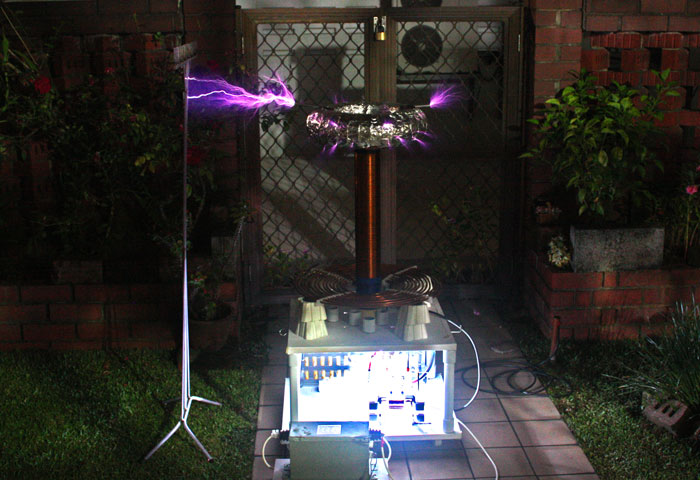
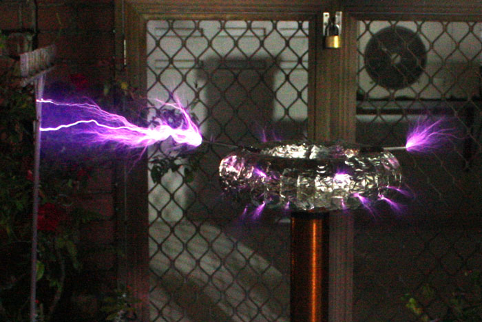
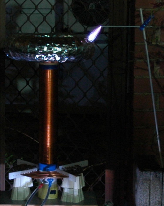
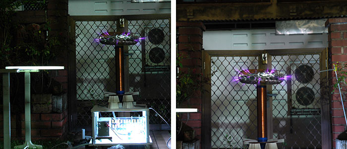
So I stuck with Turn 7.75 and took a couple of photos from there. Video included!
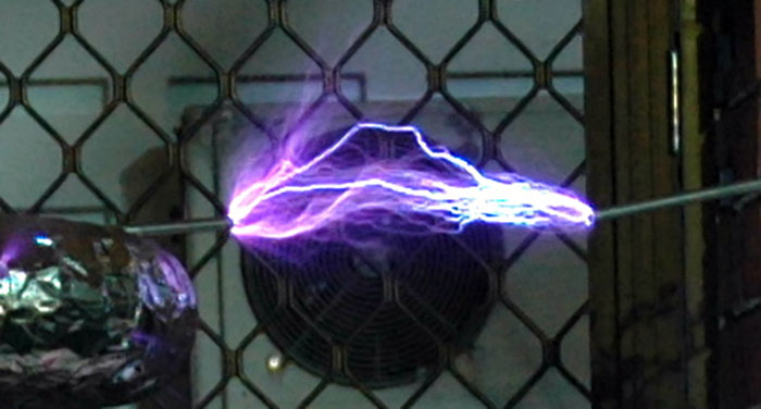
This time, I measured the distance between the breakout point and the target which the lightning arcs hit, and it turned out to be around 40-50cm! That corresponds to about 1,350,000V! Sweet!
This should end with my journey with the Tesla Coil. It’s been a really long way since I started on the project on 28th of February 2007, till today. Over a year and a half.
Performance is great! Although I’m not too sure whether it’s around the maximum it can output as I didn’t tune the spark gap after it became loose over the months, I guess I should be pretty close.
I guess that concludes this amazing project, so enjoy the pictures!